Fly back Synchronous Rectification Problems and Countermeasures
In recent years, with the continuous improvement of international energy efficiency standards, conventional Schottky diode rectifiers cannot meet the energy efficiency requirements of low-voltage and high-current output specifications (DoE Level VI in the United States, CoC V5 Tier 2 in the European Union); even with ultra-low Vf Xiao For the rectification of special base diodes, some heat sinks need to be added, which will lead to large PCB space, low power density, low efficiency, high shell temperature, and poor user experience. Using synchronous rectification MOS, in the case of the same output current, the loss is very small, which greatly improves the conversion efficiency of the whole machine.
There are many working modes of switching power supply (CCM, DCM, QR, BURST), and the synchronous rectification control IC is passively receiving synchronous mode, so it is difficult to avoid failure under any load and full voltage input conditions, the following are some common problems and improvement measures
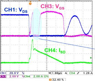
1: The MOS tube is turned on or off in advance
cause:
1) The SR IC_gate drive output is disturbed, leading to early opening
2) The internal slope detection circuit of SR IC is disturbed, and it will be turned on in advance, or it will be turned on in the first Ring
3) After the SR IC_gate is turned on, it is disturbed by the primary leakage inductance and the DS capacitor oscillation of the MOS, and it is falsely triggered to turn off the MOS.
Make an impact:
1) The gate of SR MOS is turned off in advance, which will lead to long conduction time of the diode in the body, low efficiency, and high temperature of synchronous MOS.
2) Looking at the waveform from the primary Vds or secondary Vds, there will be large and small waves (for CCM mode).
solutions:
1) Choose a good SR IC brand
2) Improve PCB layout (SRIC for extrapolated MOS)
3) Adjust the primary absorbing RCD circuit, such as absorbing a diode in series with a damping resistor
2: Primary and secondary MOS common problems
cause:
In CCM, when the primary MOS is turned on, the secondary MOS should be turned off in time and accurately. When the turn-off delay of the secondary MOS is too long, there is a possibility that the primary and secondary MOSs are common.
Make an impact:
The secondary will generate a large reverse current, which will seriously damage the MOS
solutions:
1) Select SR I with very short Turn-off Time Delay
2) Choose the right SR MOSFET (use smaller Qg)
3) Increase the drive resistance of Q1_Gate to slow down its drive speed
4) Design proper secondary RC absorption circuit parameters
3: The output voltage drops, the ripple is large, and the load capacity drops
cause:
(For synchronous rectification applications under the PSR architecture) For the PSR IC solution (BCM/QR, frequency limited to 110KHz) whose operating frequency goes to 80KHz or above under the condition of high voltage 230Vac, when the power system works at low voltage 115V (actually from 170Vac The following voltages may have the problem of output drop. The synchronous MOS is not turned on, and the diode in the body is already working, resulting in a drop in the output voltage (a PN junction voltage drop).
Make an impact:
The output voltage of Vout is dropped, unstable, and the ripple is large. In severe cases, the output voltage will drop directly to 4.2-4.5V, and the output current will also drop (only 1/2 or 2/3 of the full load)
solutions:
1) Lowering the transformer inductance and lowering the operating frequency to below 80KHz will partially improve it, but it cannot completely solve this problem.
2) Use the PSR IC of DCM, the working frequency is below 70KHz.
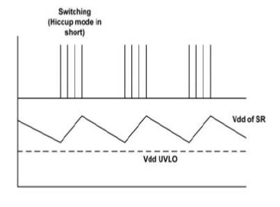
4: After the output short-circuits SCP, the temperature of the SR MOS tube is high, and the input instantaneous power increases
cause:
When the output terminal enters short-circuit protection, the primary IC enters HiccupMode. If the VCC power supply is insufficient, SR MOS enters UVLO undervoltage protection, then Isd flows into the MOS body diode. At this time, the temperature of SR MOS rises, and the input instantaneous power increases relatively.
Solutions:
1. Select a SRIC whose Vo short-circuit protection value is lower than Vdd_UVLO;
2. If the SR IC does not have Vo short-circuit protection function, you can try to increase the Vcc capacitor capacity.

